Hole dimensions: width of hole w, length of hole l
Width of hole w = smallest dimension, i.e. diameter of round hole, edge length of square hole, and width of long hole.
Length of hole l = length of long hole (largest internal dimension).
Note: The technically feasible hole diameter is determined by the thickness and the type of the material.
The approximate figure for steel, aluminium and similar material: The hole diameter should not be less than the material thickness (relation 1:1). In the case of stainless steel and steel of a higher degree of hardness the relation is less favourable. In exceptional cases, these relations may fall below this level. However, these cases need prior technical clarification.
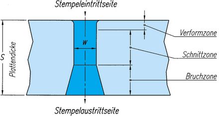
Cross section of a hole
The pattern of a hole of a perforated plate is usually slightly conical.
For this reason, the relation of the bridge c to the thickness of the plate s indicated below should not be less than 1. Otherwise, the bridges between the holes may break. In the case of screening plates, the conical form of the hole is advantageous, since it reduces the risk of holes being blocked.
Number of holes: Spacing t (pitch), width of bridge c
Two terms are used to describe the distance between the holes:
Pitch of holes t: The pitch is defined as the distance from centre of hole to centre of hole in two adjacent rows.
Width of bridge c: This signifies the smallest unperforated space between 2 holes in adjacent rows.
Note: t = w + c
In the case of the long hole, a distinction is made between bridge and side bridge.
Guideline: Approximately the same proportion of the bridge c to the thickness of the material s is applicable as for the hole diameter w (relation bridge c to thickness s approx. 1:1). Depending on the material, the hole diameter w and the pitch t, relations of less than 1 are also possible.
Raw Edge
Minimal burr formation on the outlet side of the punch is unavoidable. The degree of burr depends on the material, the tolerances of the punching tools, the wear of the tool and various other factors.
Our tools, manufactured by state-of-the-art machinery, guarantee punching with the smallest possible burr. Nevertheless, an absolutely smooth surface can be obtained only by suitable treatment (such as brushing, grinding).
Direction of Feed
The direction of feed is very important with screening plates. It indicates the direction in which the goods are carried across the plate. The best screening result is achieved if the holes are staggered across the feeding direction.
The direction of feed is defined clearly in the DIN standards 24041 and 4185. It is always parallel to dimension a1.
Sens de passage des produits
Le sens de passage est particulièrement important pour les tôles de criblage. Le sens de passage (ou sens de transport) indique la direction dans laquelle le matériau à cribler est transporté. Le meilleur résultat est obtenu lorsque les trous sont disposés en quinconce perpendiculairement au sens de transport.
Le sens de transport est défini clairement dans les normes DIN 24041 et 4185. Il est toujours parallèle à la dimension a1.
Relative open surface (open section, open area)
The relative open surface is often called "open section" or "open area". This means the percentage of open surface (holes) in relation to the perforated area (without margins).
The relative open surface is important for screening and the determination of the rate of flow as well as for the calculation of the load-bearing capacity and weight saving.
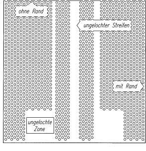
Blank Margins, Blank Stripes or Areas
The blank margin is the distance from the plate’s edge to the first line of punched holes. The blank margin is dependent on the spacing of the tool and the dimensions of the plate.
If no indications are given concerning the blank margins, the term "smallest possible blank margin" is often used. In this case, the smallest possible blank margins are chosen under consideration of the tools used.
Plates without blank margins are usually cut out of larger plates or punched in the all-across press by lengthwise cutting from a coil.
Unperforated stripes or areas may be manufactured by using the respective tool variation, blank advancing, by automatic tool control, or by double action. However, in this case, particular attention must be given to the tensions in the plate (see levelness).
Levelness, Sabre Shape
Levelness:
Generally, perforated plates are levelled once mechanically in order to keep their levelness within the DIN standards. Particularly in the case of
- dissimilar side margins
- unperforated areas or stripes
- large open surface
- certain materials
residual tensions in the plate are sometimes unavoidable. In such cases, it is essential to clarify beforehand the levelness required and the resulting additional treatment.
Sabre Shape:
Perforated plates with dissimilar side margins e1, e2 may become sabre shaped. The extent of the sabre shape is affected by the material, the material thickness, the length and width of the plate and the relative open surface A0.
While the sabre shape of the plate can be eliminated by cutting, the sabre shape of the perforated area cannot be eliminated. In this case too, it is advisable to clarify the admissible tolerances.
Beginning of perforated area
For tool-related reasons, the punch and the matrix are arranged in the tool at distances larger than those of the holes in the plate. This results in a hole pattern with incomplete rows of holes (double staggered rows), also called "big beginning"; the hole pattern is complete only after the second stroke.
Should you wish the complete hole pattern on the first stroke (normally staggered rows or "small beginning") please indicate this in your enquiry.
DF Lochbleche GmbH & Co KG
Franz-Meguin-Straße 20
D-66763
Dillingen
Tel +49 6831 7003-0
Fax +49 6831 704076
info@df-lochbleche.de
www.df-lochbleche.de


